How Big of a Fuse Do I Need?
This is one of the most common questions we’re asked and the answer is not always cut and dry. The thought process is typically . . . My electric fan requires 25A so I need a 25A fuse, right? Well . . . maybe.
The Basics
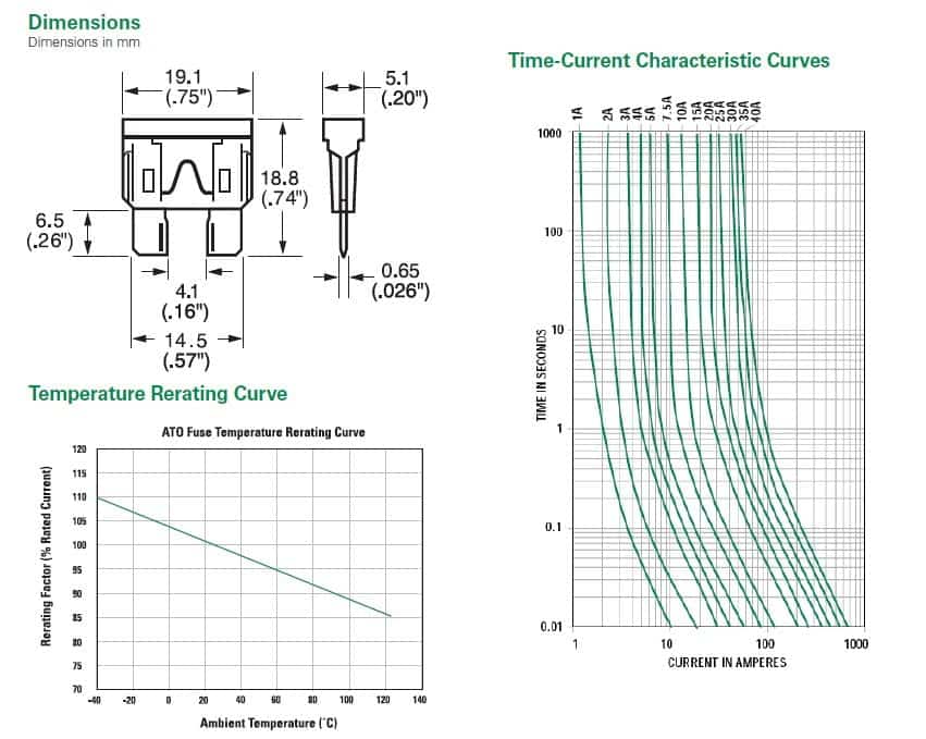
Fuses fail based on current vs time. A typical rule of thumb is that a typical automotive “blade” fuse requires double its current rating for 2s to open. So, a 25A ATC fuse would require 50A passing through it for 2s to open (or blow). And while this is an excellent starting point, the rabbit hole is a bit deeper. So, to determine the correct fuse size, you’ll need to consider a few things:
- The continuous current required of the accessory
- The maximum current required of the accessory
- The inrush current requirement at startup of the accessory
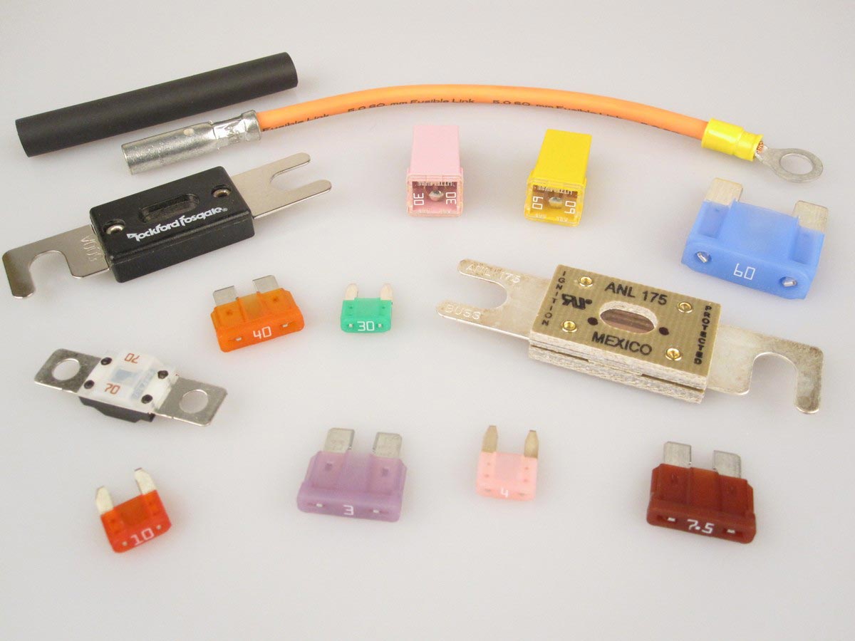
All of the big fuse manufacturers which manufacture quality fuses manufacture them to comply with standards set forth by the SAE (Society of Automotive Engineers). And that’s why we sell them. Consider the following time vs current failure charts.
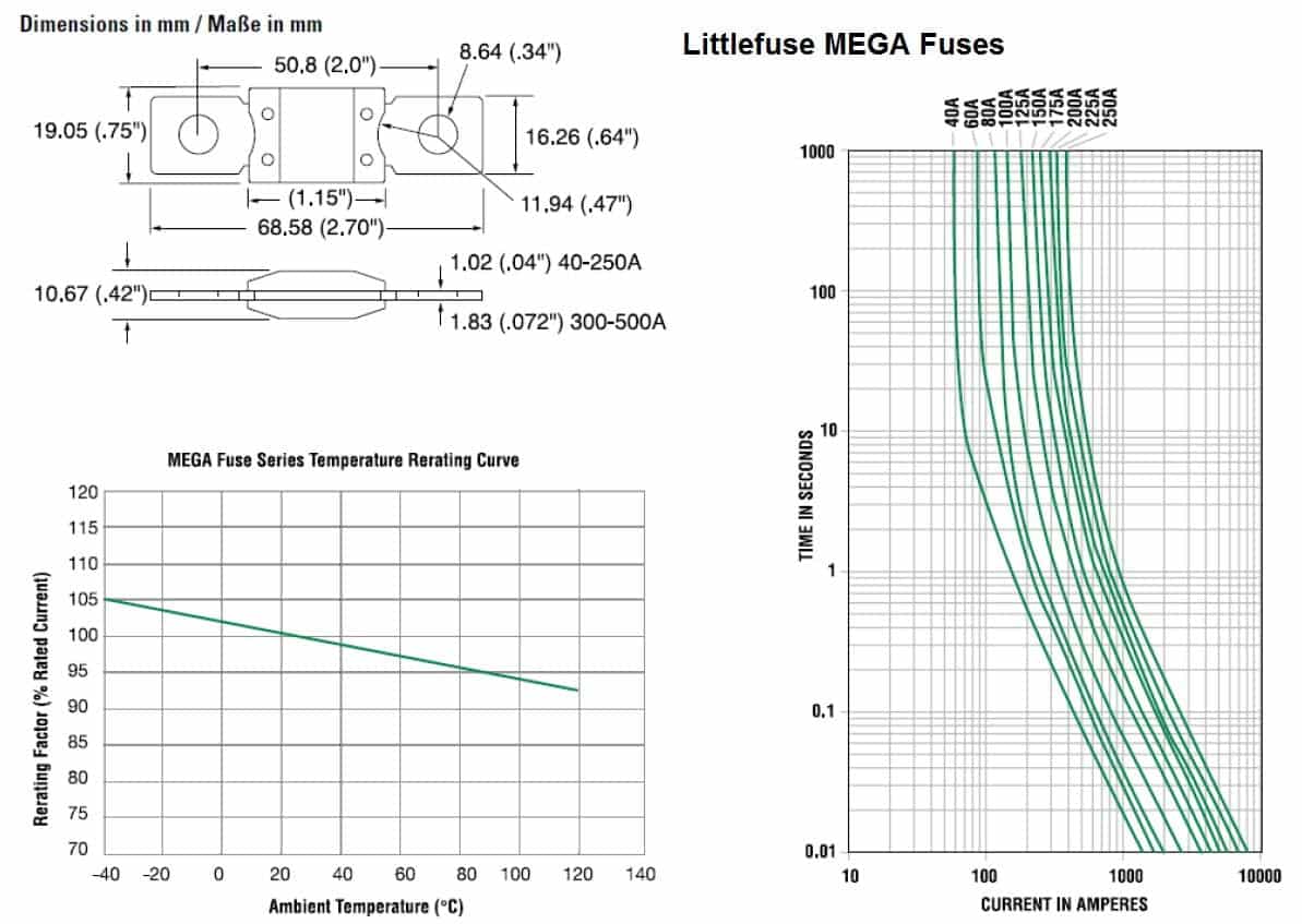
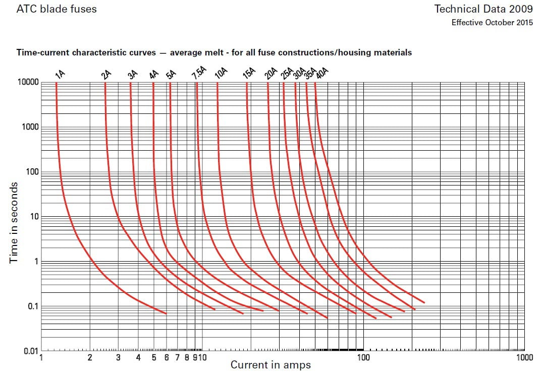
Did you happen to notice that a 100A Littlefuse MEGA Fuse can pass more than 300A for 1s? That’s a LOT.
So, how do we choose the correct fuse size and type? Well, first we’d better know a bit about the accessory we’re powering.
Example 1 – A Sealed Beam Headlight
A headlight is a great example. A traditional headlight filament is really just a short circuit in a vacuum. When powering it up, it behaves as a dead short when cold. As current flows through the filament, the filament warms. The heat causes the filament’s resistance to increase. This increased resistance lowers the current demand of the filament. This heat causes voltage drop across the filament, just like a resistor – a transducer which converts electrical energy to heat. So, a headlight behaves as a short circuit on power up, then as a resistor when operating. The current required to turn the headlight on when cold is referred to as its inrush current.
The last photo shows how to properly connect the meters to measure both current and voltage – the big alligators go to the meter measuring current and the smaller alligators to the meter measuring voltage. Wanna’ become the expert with a DMM? Well, you’ll learn how in my first book, Automotive Wiring and Electrical Systems.


We can use a little Ohm’s Law to calculate the approximate resistance of the filament both cold and hot. Ohm’s Law describes the relationship between current, voltage, and resistance. It’s quite simply I = E / R where:
- I = Current in Amperes
- E = Voltage in Volts
- R = Resistance in Ohms
So, let’s do some algebra and rearrange that formula to solve for R so we can calculate the resistance of the filament. This yields R = E / I
Filament resistance when cold = 13.8 Volts / 6.63 Amps = 2.08 Ohms
Filament resistance when hot = 13.84 / 4.196 = 3.30 Ohms
The resistance is 58% higher when it’s warm than cold. [Do the math on the inrush current vs in use . . . and that’s why I love math.]
A circuit like this could make use of nearly any fuse type. I’d use a 7.5A fuse for one headlight and a 15A fuse for two.
Example 2 – An Electric Fan
An electric fan is a totally different animal. The coil of wire in the motor is highly inductive. Inductive loads are difficult to power up so they require far greater inrush current than resistive loads. [Think about the noise the A/C condenser makes alongside your house when it comes on. The inrush current is so high that start up capacitors are used to offset it.] In addition, the motor drives a fan and the blades of the fan do work moving air, which adds significantly to the load placed on the motor. The net of both will be reflected in the current consumption of the fan in use. A load like this is considered to be a reactive load, which is any load that has any combination of resistance, inductance, or capacitance.
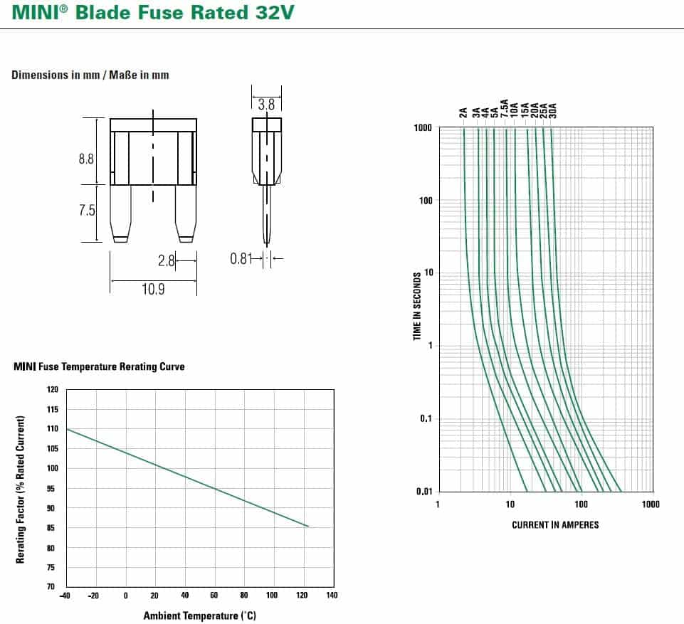
Once the fan is powered up and the coil of wire is heated, the load the motor places on the charging system is reduced significantly. Electric fans can require up to 4x their continuous current rating at start-up! Reactive loads have far greater inrush current than resistive ones. Here’s the skinny on a 16″ Spal Straight Blade Fan which requires approximately 25A of current at 13.8 Volts. We acquired this data when doing a failure analysis on our 40A MINI Fuses. Notice the difference in current to the fan as voltage increases!

We consider 13.8 VDC to be the typical running Voltage of a vehicle with a 12V battery and a correctly designed and functioning charging system. This assumes the vehicle has reached operating temperature and the battery has been fully recharged from starting the engine.
A circuit like this would require a quality 40A fuse with high in-rush current capability. I skip MINI and ATC / ATO fuses for the big fans and use a MAXI, MIDI, or JCase as they have much higher inrush capability. Incidentally, our Fan Relay Kits are fully compatible with such fans when swapping the 40A MINI fuses to our 30A MINI Circuit Breakers (they fit perfectly) as they will tolerate nearly 6x the in-rush current as the 40A MINI fuse.
Safety Considerations
OK, so now that we’ve chosen the correct fuse size based on the needs of the accessory, the next step is safety. Following are some excellent guidelines for stranded copper wire:
- 18 AWG is rated to 7.5A
- 16 AWG is rated to 10A
- 14 AWG is rated to 15A
- 12 AWG is rated to 20A
- 10 AWG is rated to 30A
- 8 AWG is rated to 60A
- 6 AWG is rated to 100A
- 4 AWG is rated to 150A
- 2 AWG is rated to 225A
- 1/0 AWG is rated to 300A
Certainly, length is a factor. So consider all of the above to be excellent guidelines to minimize Voltage drop for circuits of 15ft or less.
Let’s Put this Knowledge to Work!
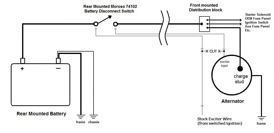
Let’s say you had an electric fuel pump in the tank which required 20A to achieve the maximum fuel flow rating. The total length of wire between the power wire from the battery to fuse holder, from the fuse holder to the fuel pump relay, and from the fuel pump relay to the fuel pump in the tank was 20ft. The length of the ground wire from the battery negative to the body was 1ft and the length of ground wire from the fuel pump to the body in the rear was 2ft. That gives us a total circuit length of 23ft. [This also assumes you know the proper procedures as it pertains to grounding – covered fully in our Getting Grounded blog.]
Here’s the diagram of the circuit:

Which of the following is the correct choice to optimize this circuit?
A – 12 AWG Wire throughout* with a 20A fuse
B – 12 AWG Wire throughout* with a 25A fuse
C – 10 AWG Wire throughout* with a 20A fuse
D – 10 AWG Wire throughout* with a 30A fuse
*The wiring to terminals 85 and 86 of the relay excepted . . . as they can be as small as 20 AWG.
If you guessed C, then you’d be right. As the total circuit length is 8ft longer than 15ft, going up one size in wire is required to offset the voltage drop. The 20A fuse offers the pump the greatest protection. We don’t upsize the fuse, just the wire. And we’re well within the acceptable fusing range of 10 AWG.
Incidentally, let’s say that you chose A. The net result would be excessive Voltage drop in the circuit when your fuel pump required the most current – and that would be the point at maximum RPM. That’s a bad place to starve a fuel pump for current! And guess what, you can run into the very same problem when using CHEAP parts. But, that’s for another blog . . .
When it comes to fuses, we only sell the best. Here’s a link to all of the Fuses and Fuse Kits we offer.