Getting Grounded – The Fundamentals of Grounding
Note: This originally appeared in Volume 2, Number 2 of Street Rod Life Magazine.
Let’s start with the basics. Electrically speaking, ground is a point of commonality and nothing more. Since no automobile that I’ve seen has a rod driven into the ground next to it, where is ground in your car? Ask ten enthusiasts where ground is in their car and they’ll immediately point to the negative battery terminal. Are they correct? No. Let me explain.
With the engine off, current flows from the battery through the accessory and then returns to the battery negative terminal.* With the engine running in a vehicle with a correctly functioning charging system, current flows from the alternator through the accessory and then returns to the case of the alternator. Since ground is a point of commonality, ground would be the point at which the accessory, the battery, and the alternator are grounded. That could be the frame, the body, or both. Keep in mind this applies to both positive- and negative-ground systems although the specifics here will pertain to the latter.
*Electron theory states that current travels in the reverse of what I’ve spelled out, but the net result is the same no matter which theory you subscribe to.
Unit-body VS Body-on-Frame Vehicles
In a unit-body vehicle, ground is the body as there is no frame, only sub-frames. Some body-on-frame vehicles include the frame in the grounding scheme and others do not. This is important to understand as body-on-frame vehicles have rubber bushings between the body and frame electrically isolating them from one another.
OEM Grounding Schemes
It’s important to understand how the original equipment manufacturers (OEMs) ground vehicles and how that impacts modifying or servicing a particular vehicle. Maybe you’re plucking an LS2 out of a wrecked ’06 GTO and plan to transplant it into your street rod. Maybe you’re installing a kilo-buck aluminum radiator to improve the cooling. Maybe you’re relocating the battery to the trunk to clean up the engine bay in an effort to earn style points with the judges. Maybe you’re doing all three. Understanding the OEM grounding schemes will be paramount in order to execute any of the above correctly.
The OEM’s have put a lot of thought into the ground cables you see under the hood of a stock vehicle. Let’s discuss the specifics.
Stock vehicles most commonly have one of two types of battery negative cables:
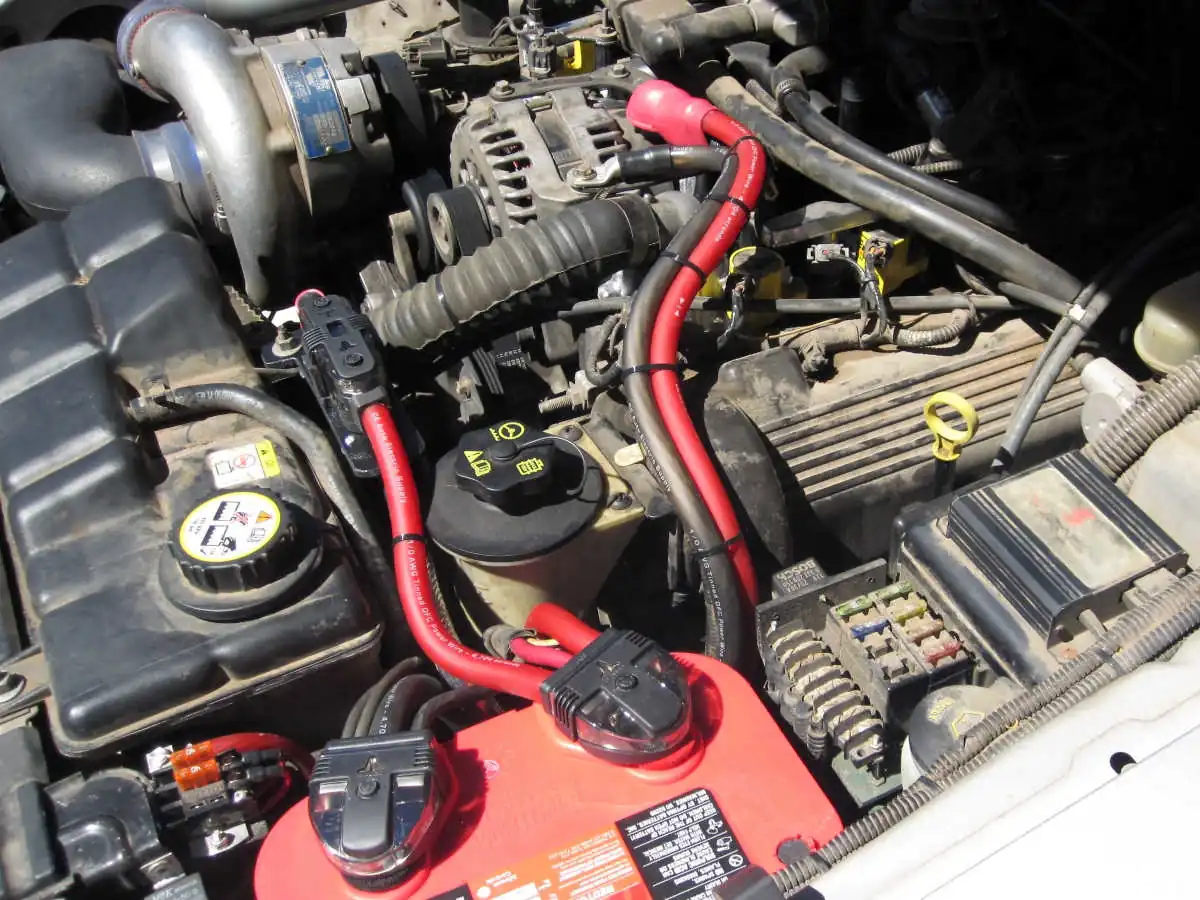
Type 1 – The negative cable assembly has a large cable, typically 4 AWG, that connects to the cylinder head or engine block. (I’ve also seen cases where this cable was bolted to the alternator bracket.) In addition, it has one or more smaller ground wires that connect to the body, wiring harness, or both. The larger cable is the return path for the starter and the alternator. The smaller wire(s) are the return path(s) for the accessories and are often referred to as body grounds.
Type 2 – The negative cable assembly has a single large cable, typically also 4 AWG. It connects to the cylinder head or engine block at its end. Along its run, it also connects to the body. This single cable approach is the return path for the starter, alternator, and accessories. This type of negative battery cable assembly is most often found on import vehicles but can also be found on modern vehicles manufactured by the big three.
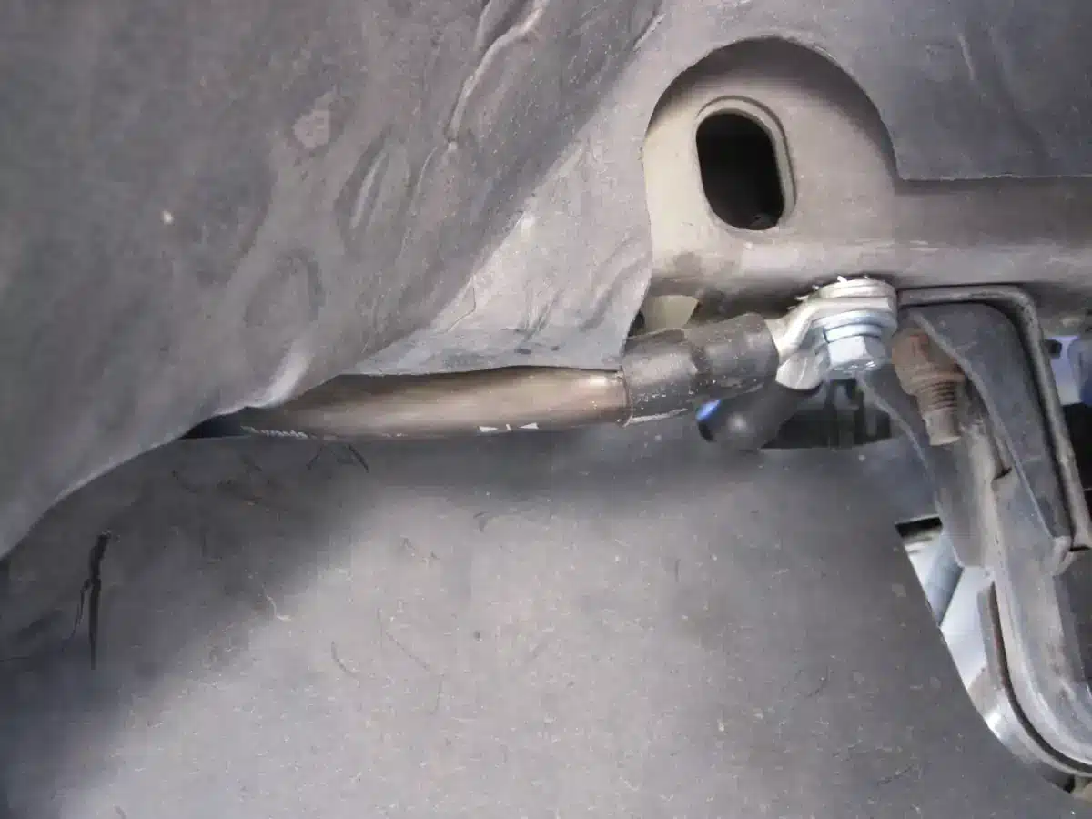
In addition to the battery negative cable, you’ll typically see at least one ground strap. Depending on the particular vehicle, this ground strap may connect the body to the frame, the engine to the body, the engine to the frame, etc. Later model vehicles with electronic fuel injection, aluminum radiators, or both will have a plethora of grounding in comparison to classics. Next time you’re at the car show, look under the hood of a new vehicle and you’ll see what I mean.

Faulty Grounds
Over time, grounds can be a source of various vehicle electrical problems. The connection between the termination and wire, the termination and the vehicle ground, or both, can break down over time causing its resistance to increase. This can be exacerbated by heat, high current, or both. As vehicles age, this is a normal part of the aging process.
Consider how many vehicles you see leave the cruise in the evening with yellow headlights. The yellow hue is an indication of voltage drop between the alternator and the bulbs. When troubleshooting such a circuit, you’ll find that the voltage drop on the ground side of the headlight circuit is a significant factor in its overall performance.
Grounds break down over time for various reasons.
- Breakdown of the termination itself. Oxygen in the air causes copper cable and copper eyelets to oxidize. Water entering the termination and galvanic corrosion (corrosion between dissimilar metals) are other factors that can cause the termination to break down. Any such breakdown results in the resistance of the termination increasing as it breaks down from the inside out. This in turn causes heat which accelerates the process.
- Mechanical failures. The connection between the termination and the vehicle ground can deteriorate over time. This can be caused by rust, heat, or simply a loose fastener that holds the ground in place.
At some point, the resistance of a given ground can exceed the resistance of an alternative ground path. For example, let’s say the connection of the 4 AWG ground cable from the battery negative to the block breaks down over time. The starter may seek ground through the block to the cylinder head, through the cylinder head to the intake manifold, through the intake manifold to the carburetor, through the carburetor to the body via that braided steel throttle cable bolted to the firewall, through the body ground to the battery negative terminal. Something’s gonna’ give at some point as the current required by the starter greatly exceeds the ampacity of the throttle cable and the body ground.
Grounds are maintenance connections and should from time to time be checked for tightness and integrity. Better to do this when your vehicle is in your garage within walking distance of your tool box versus on the side of the road out of necessity.
The Art of Grounding Properly
Generally speaking, making solid, low-resistance ground connections that will stand the test of time is quite easy. Here’s my recipe:
- Invest in the correct tools to make proper electrical terminations. Some choose to solder and others choose to crimp. Whichever method you prefer, ensure that you’re performing your terminations correctly.
- Use tin-plated ring terminals and cable eyelets whenever possible. Tin-plated parts have higher resistance to corrosion and oxidation as compared to bare copper and non-plated brass parts.
- Insulate all terminations with adhesive lined heat shrink tubing. This keeps the elements out, which prevents the termination from breaking down from the inside out over time.
- Prepare the vehicle surface properly by removing paint and primer to ensure a low resistance connection between ring terminals/cable eyelets and the metal.
- Protect the metal from rusting with white lithium grease. I’ve used this for 25 years now and it holds up well over time, protects the bare metal from rust, and doesn’t impede the flow of current between the ring terminal/cable eyelet and the metal.
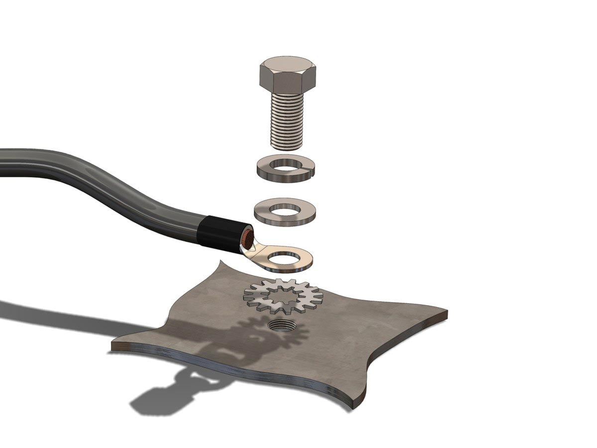
- Use internal/external star washers between the ring terminal/eyelet and the metal to provide a good bite into the metal and into the underside of the eyelet.
- Use a lock washer and flat washer under the head of the bolt or sheet metal screw to keep it from backing out over time or from resonance caused from a gnarly powerplant with a lumpy camshaft.
- Ensure all hardware that you use is plated.

When it comes to battery cable, I also prefer tinned Oxygen Free Copper (OFC) even though it sells for a premium as compared to standard battery cable. Such cable holds up better over time. I like to do electrical projects once and not have to go back and fix them at a later time. Investing in quality parts the first go saves time and money in the long haul.
Grounding Considerations When Adding a Host of High Current Accessories
We street rodders and hot rodders typically add a host of aftermarket electrical and electronic parts to our vehicles. Guess what, our ’50 Merc wasn’t designed to accommodate them. No problem, we can improve on the original design. Let’s say we wanted to add a pair of electric fans and an electric fuel pump. Since the body of this vehicle is 65+ years old now, it’s really not the best way to ground our new accessories as the spot welds connecting to body together haven’t aged gracefully.
Since the Merc’ is a body on frame vehicle, it’s better to make use of the frame for the return path for these new accessories (assuming of course that it’s not rotted out). Connecting the ground leads of the fuel pump and electric fans to the frame rails is simple. Install eyelets on the wires, drill and tap holes for Grade 5 bolts, and bolt them in place. Then, run two new ground cables from the charging system to the frame rail. One of these cables will be from the battery negative terminal and the other will be from the case of the alternator (or one of its mounting points). Connect these two cables to the frame at the same point. I prefer to use 3/8″ bolts for all frame grounds, but 5/16″ are OK as well for stuff like this. 8 AWG cables would be fine in this example.
Follow the eight steps I outline above when doing so. The net result is that you’ve just designed and implemented a low resistance return path between the fans and the charging system, optimizing the relationship between the two and minimizing voltage drop to the fuel pump and fans.
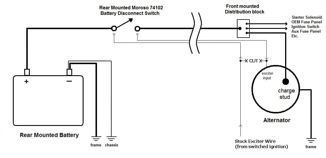
Grounding Considerations When Relocating the Battery
When relocating the battery to the rear of the vehicle, the most oft-overlooked part of this installation is the body ground for the accessories. Connecting the negative terminal of the battery to the body preserves the return path between the battery to the accessories through the body as discussed earlier. I typically use 8 AWG cable for this.
The other side of the equation is to provide a high-current return path between the battery and the alternator and starter. What’s the best way to do that? Does this differ for unit-body and body-on-frame vehicles?
For both unit-body and body-on-frame vehicles, I prefer to use the frame rails for this return path. I’ll ground the battery negative to the frame rail, then I’ll ground the engine block to the frame rail on the same side of the vehicle with the same size cable I’ve used for the battery to frame ground. Follow the eight steps I outline above when doing so, and you’ve created an excellent return path. The size of the battery cable you’ll use for both the positive and ground is a function of how much current the starter requires and the distance between the battery and starter. I typically use 2 AWG battery cable for lower compression engines and 1/0 AWG battery cable for higher compression engines in street rods and hot rods.


Some builders, and even a few aftermarket automotive electrical companies, prefer to run the negative battery cable from the battery all the way to the engine block. I’ve heard various reasons cited over the years, each with an equal amount of conviction. Unfortunately, when I’ve measured voltage drop over a length of cable as compared to using the vehicle frame rails as I’ve outlined above, the vehicle frame rails offer less voltage drop. I’d love for someone to prove me wrong, as I could sell a lot more cable if it were true.
Grounding Considerations When Installing an Aluminum Radiator
Putting an aluminum radiator in your street rod is one of the most common improvements you can make. When doing so, install the following ground straps, at minimum:
- Rear end housing to frame rail
- Core support to frame rail
- Battery negative to frame rail
- Bell housing to firewall
I typically use 8 AWG cables for this. These cables are designed to prevent electrolysis from manifesting itself in the coolant, a byproduct of an improperly grounded vehicle. As aluminum is a very soft metal, the electrolysis can actually consume the radiator from the inside out as it seeks its way to ground. The above cables should be installed before installing an aluminum radiator to create a foundation that resists electrolysis.
So, why ground the rear end? Good question. Studies have shown that electrolysis can be either alternating current (AC) or direct current (DC) in nature. AC electrolysis can be generated by the friction between the ring and pinion gears in the rear end, travel up the drive shaft, and work its way into the coolant. Such a ground strap can prevent this from happening. Weird, I know.
Grounding Considerations When Installing a High Output Alternator
I consider a high output alternator any alternator that is larger than the one the factory installed. You’re obviously installing such an alternator because of the additional current required by the accessories you’re also adding. The stock return path leaves much to desire. Your goal is to improve the return path between the alternator and the accessories. The grounding scheme presented above in “Grounding Considerations When Adding a Host of High Current Accessories” is exactly how you do this. Use 8 AWG cable for alternators making up to 90A, use 4 AWG cable for alternators making up to 170A, use 2 AWG cable for alternators making up to 225A, and use 1/0 AWG cable for alternators making up to 300A.
Grounding Considerations When Installing a High Performance Ignition System
Any high performance ignition system requires proper grounding to get the best performance. This is simple; connect both cylinder heads together with a ground cable (or strap) and then continue on from one cylinder head to the frame rail. Connect the battery negative to the frame rail on the same side of the vehicle. I typically use 8 AWG cables. This improves the return path from a high output coil and ignition box, across the gap of the spark plug, and then on to ground. Look in the manual of any high performance ignition box and you’ll see this outlined but nobody ever does it! Simple.
Grounding Considerations When Adding EFI
If you’re installing an aftermarket electronic fuel injection system (EFI), then you should absolutely follow the instructions outlined in the installation manual in regards to grounding. Note that they are VERY specific.
First, the main ground lead should be run directly to the battery negative terminal. The battery is the single best filter in your vehicle. Grounding the ECU at the battery directly makes the best use of this filter in an effort to reduce noise transmitted to the ECU which can cause it to function erratically. This often means extending the ground and power leads when installing such a system in a vehicle in which you’ve also relocated the battery.
Secondly, many aftermarket EFI systems have additional ground leads that are to be connected elsewhere and not to be grounded to the same point as the main ground lead. Follow the instructions to the letter. You’ll thank me later.
Grounding Considerations for Fiberglass Vehicles
Obviously, you won’t be grounding accessories to the body of a fiberglass vehicle, not unless you want to be the laughing stock of your peers when you call for their assistance. I’ve always used the frame for the return path for everything: the charging system, accessories, etc. Under hood, I’ll ground all accessories to the frame no differently than I would to the body of a steel-bodied vehicle. The only difference being that all grounds to the frame must be drilled and tapped.
It’s simple to install ground distribution points of suitable current behind the dash and in the rear of the vehicle to facilitate easy connections for the ground leads for lighting and accessories. Then, connect these ground distribution points to the frame via 8 AWG or 4 AWG cable depending on how much total current the distribution point must pass. Ground high current or noisy accessories (like ignition boxes, fuel pumps, fans, lighting, etc.) and noise-sensitive components separately to isolate them from one another as much as possible. Multiple ground distribution points connected to various points on the frame works quite well.
")
Planning for Success
If you’ve read any of my books, you know I am a proponent of proper planning. Unfortunately, wiring a vehicle is all too often the very last thing to do be undertaken. Furthermore, proper grounding is typically implemented only after things don’t work or don’t work well. Now you know better so plan accordingly and ground it correctly. This will keep you driving your street rod versus troubleshooting it.
Tony Candela
Update
Since this article was published several years ago, we’ve added a ton of new products. Here are links to the great many products we offer that will help get you grounded: