

The Olds’ – Part 4, Upgrading to Multi-Port Fuel Injection
My Olds’ has been fuel injected for a long time now – since 2010 if you can believe that. I believe I was the first to do a Holley HP system with twin throttle bodies on a roots blown engine and got a lot of miles out of that combo. I touched on the reasons why the upgrade to MPFI* was next on my radar in Part 3 – it was time.
*MPFI, or Multi Port Fuel Injection, typically implies individual injectors for each “port” or intake runner. This is a little bit different here as all injectors are in a plate above the blower, but for the sake of this discussion we’ll just roll with it. Some refer to this type of system as Throttle Body Injection (TBI) or even Plate Injection.
Planning
I’m a planner. I never start a new project without having all (or at least most) of the parts in front of me. So, I spent a few months determining how to approach this, what parts to use, and gathering them. So, I chose the following:
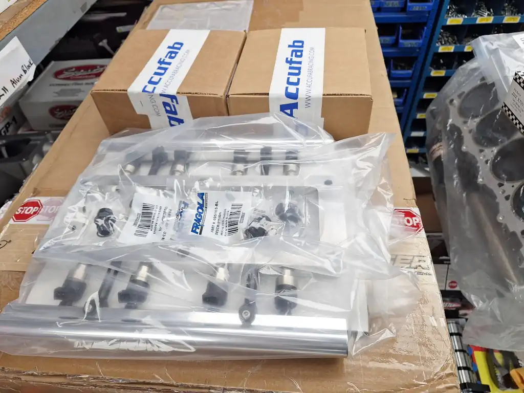
- (2) Accufab Four Barrel 4150 Throttle Bodies, Black Billet
- (1) Custom Injector Plate & Fuel Rails (from Beck Racing Engines)
- (1) 83 lb/hr Performance Fuel Injectors – Set of 8 (Holley part # 522-838)
Each throttle body can flow 1215 cfm and the math worked our perfectly for this set of injectors at 43psi to give me more than enough headroom to add extra boost should the need arise (it just won’t . . . )
Now, when you take on a project as this one, I don’t care how prepared you are, you’re just not going to have all of the fittings on the shelf you’ll need. Yeah, no – this fuel line running over this-a-way with that 45deg fitting doesn’t look right . . . so, best to have a good supplier of fittings, adapters, hose, etc. on speed dial! Also, I had some concerns. The fuel system I’ve been running for the last 15 years – was it up to the task?
I leaned on my experts at Aeromotive and MagnaFuel and they agreed that it should be no problem. This brought another question – what condition were the lines in? Close inspection on cut pieces of the original AN fuel lines showed, nice supple rubber that had shown no signs of rot. I remember paying BIG $$ for the Earls stuff when I did the conversion to begin with. It was clear to me now why that was money well spent.
Sub-Projects
I like to split projects as this one into sub-projects, as I outline in my books. So, I separated this one into the following:
- Remove the Old Components
- Install the New Components
- Plumbing
- Electrical
- Startup & Tuning
So, let’s get to it!
Remove the Old Components
I removed the original throttle bodies, linkage, gaskets, carb adapter, fuel distribution block, and fuel pressure regulator. Anytime you work on your fuel system, you really should be very conscious of the highly flammable fuel vapor which can escape from the lines when they’re just sitting there unattached. I keep male and female AN caps and plugs on hand for just that reason. Cap these lines off and be safe! Once all these components were off, the scale of the project grew – doesn’t it always?


Install the New Components
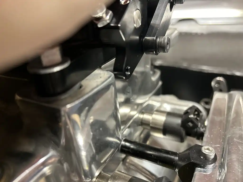
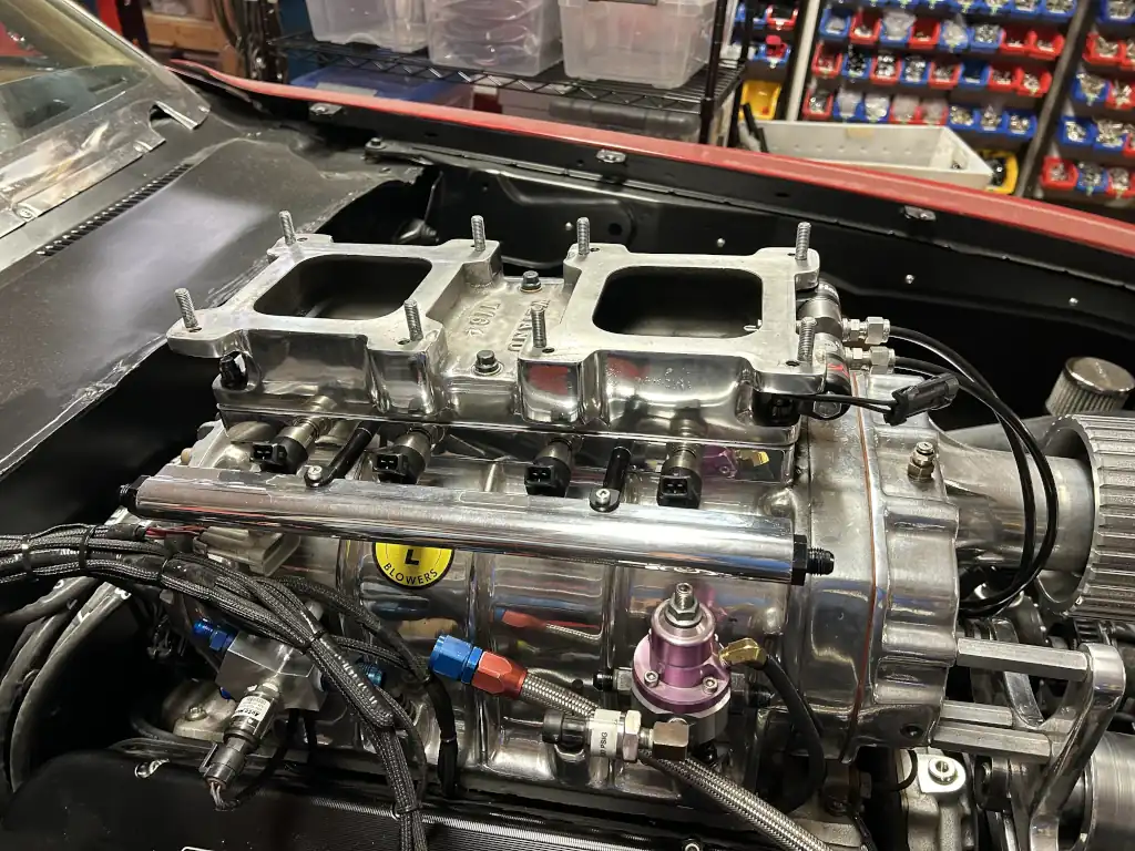
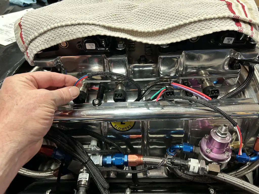
The injector plate sits on top of the blower and the carb adapter on top of that, sandwiching the plate between the two. This locates the fuel rails in close proximity to the fuel distribution block and regulator so this was job # 1. I modified the mount for the fuel distribution block and made a new mounting bracket for the fuel pressure regulator that would permit these parts to live in the same area and not run into the fuel rails. I took my time here and came up with nice solutions for both.


Finally, time to put some of these BRAND NEW shiny parts on the engine! A screened gasket goes on top of the blower (to keep the rocks out), then the injector plate, and then a standard gasket on top of the injector plate. I had both. However, I did not have studs of the correct length to secure these parts to the blower.


Challenge #1 – This project came to a halt fast. It took me a week to chase down studs of the correct height which I could use to secure the carb adapter and injector plate to the blower. Once I had those in hand I had these pieces mated and torqued in minutes! Yeah baby!
Challenge #2 – The mounting holes in the Accufab throttle bodies are drilled right on the money at 5/16″ – which won’t allow either throttle body to fit down over the carb studs. I went 1/32″ up on all four holes for each and wallah – perfect fit. Here we go! Not so fast . . .
Challenge #3 – The Accufab throttle bodies have the throttle blades located directly in the middle (height wise) of the throttle body. The throttle levers on these are a function of that and they run right into the carb adapter when actuating them. OK, so does the scoop at least fit with good clearance? Yeah, nope. The top of the arms run right into that. Perfect. So, I pulled the carb adapter back off and headed to my buddy Garry’s shop with it, the throttle bodies, all gaskets, and the scoop. He milled two nice reliefs in the carb adapter to clear the lower halves of the throttle levers and we ground, sanded, and contoured the top ends of the throttle levers to clear the scoop. This took 3-4 hours and cost me several beers that evening for his time!


Back in the shop with parts that actually fit together, I reassembled all of this and was ready to move onto the next step. I could already see the linkage was going to be a challenge . . . so, let’s get to it. I had parts laying around to connect the throttle levers via the lower bolt holes and that came out nice. However, the throttle cable was way too short (it now needed to be connected to the front throttle body, not the rear as before) and a throttle cable bracket . . . hmmm. A quick trip to Ramjet’s Speed Shop in Phoenix and I had the Lokar throttle cable I needed. The bracket, that was another story.
Challenge #4 – Stalled again with no simple solution in sight. This throttle cable bracket turned out to be many nights of searching for a part that didn’t exist – at least how I envisioned what I needed. So, I did what any right minded gearhead would do – modified one! I got out the big channel locks, secured my original in my Wilton vise, and bent it into the shape I needed it to be to get the approach angle I needed. Perfect! It would be another few evenings of dickin’ with the location of the throttle cable in the bracket itself before I could achieve wide open throttle with ease from the pedal.
From here, it was all downhill!


Plumbing
I pulled out my collection of AN line and fittings and realized that I had most of what I needed. Well, right after my buddy Motor Mike hooked me up with some -6 45deg swivels that is! I had the new lines made up in short order and everything fit nice – tight, but nice.


Electrical
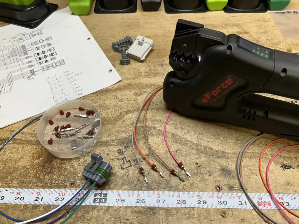
This is my wheelhouse. I had to wire the injectors, TPS, and IACs.
Injectors
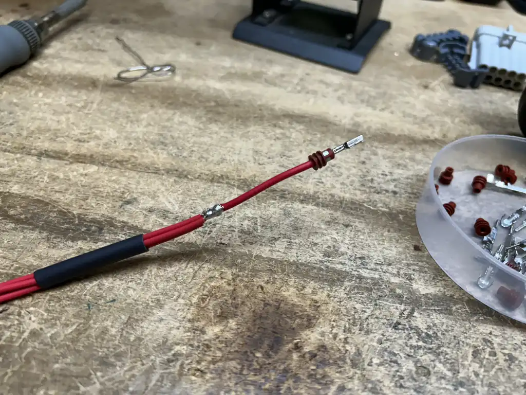
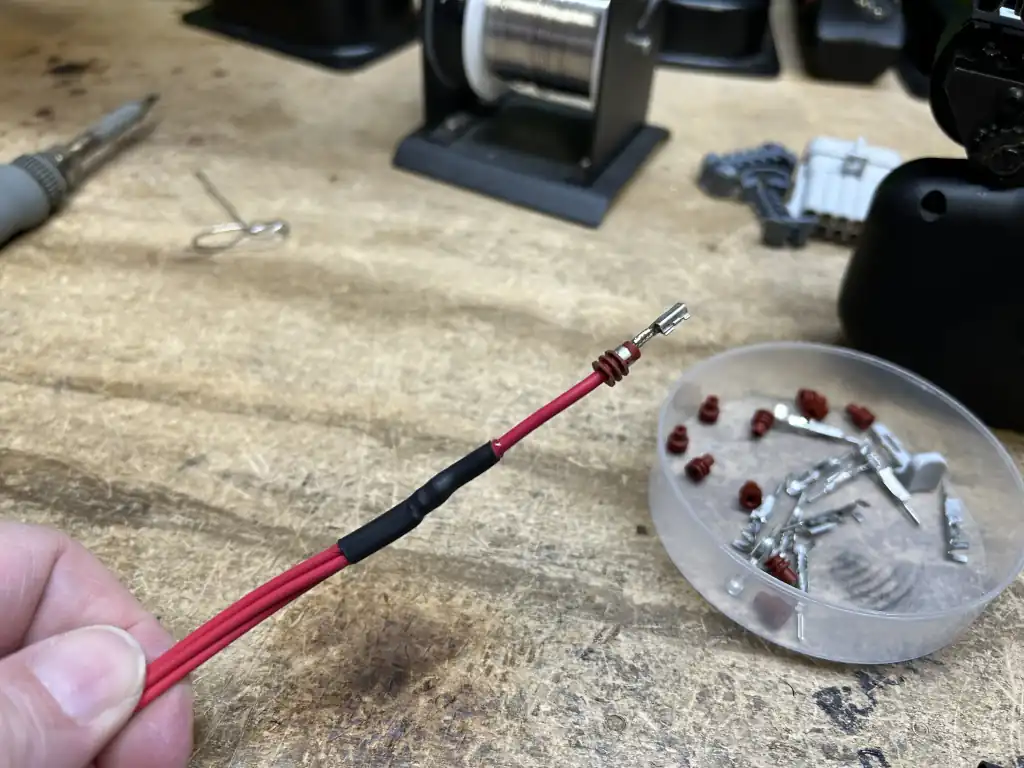
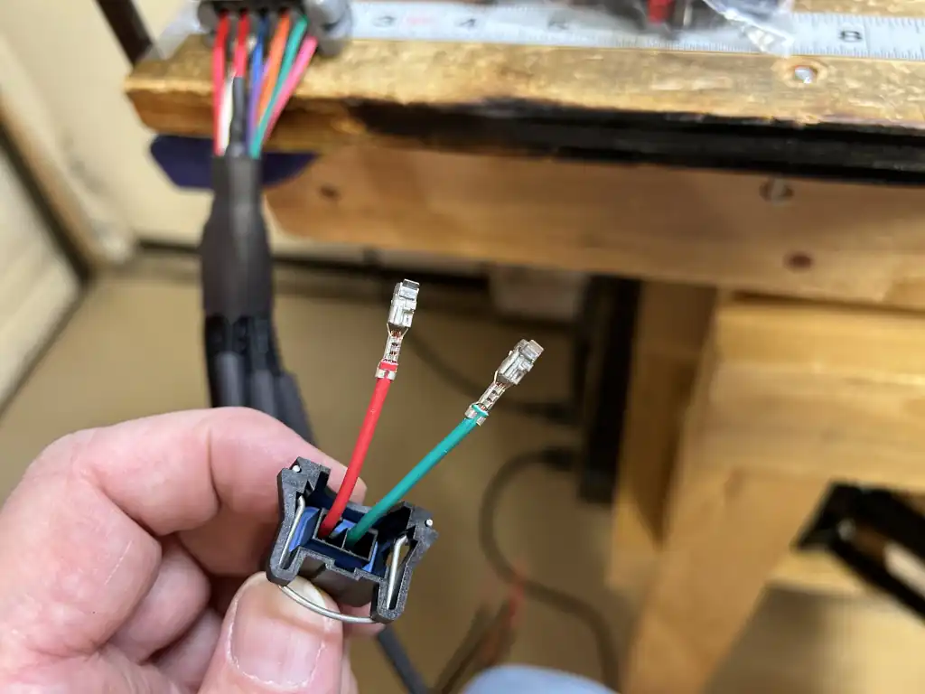
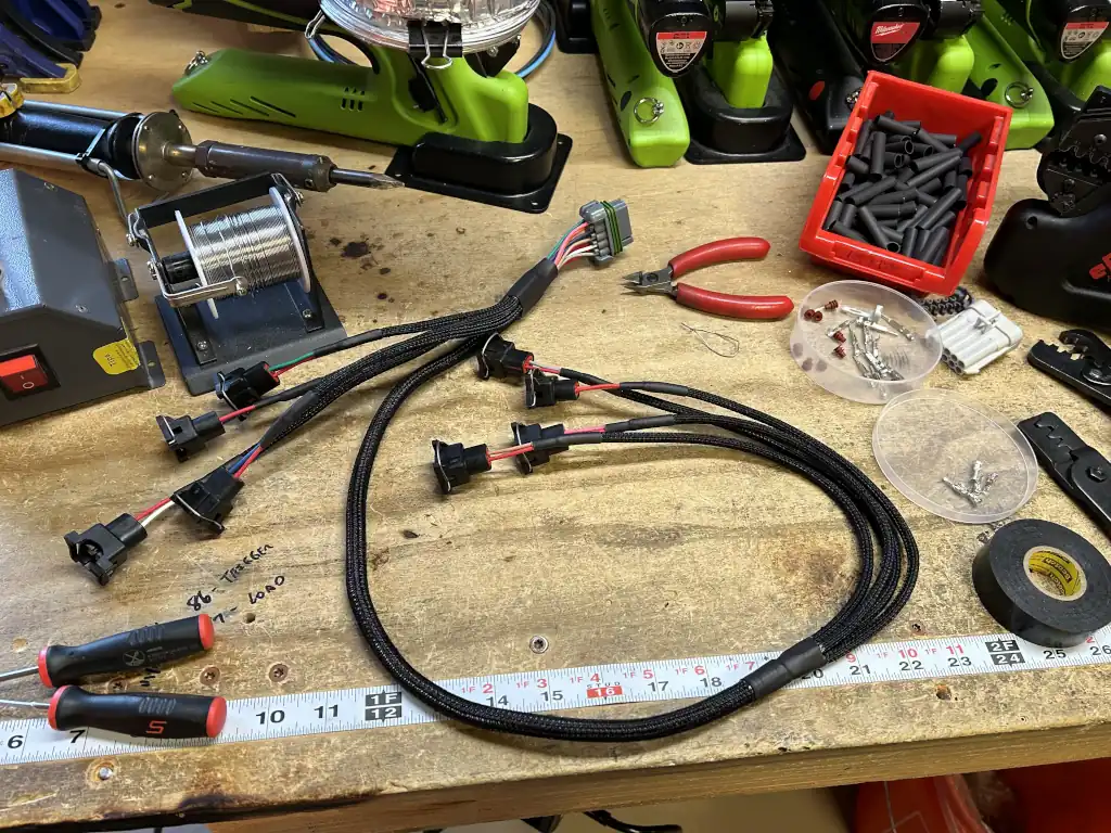
I had all of the connectors I needed on hand for the Bosch/EV1 injectors and we stock the correctly keyed Metri-Pack Series 10-Position Connector to mate with the Holley harness. I used our 20 AWG TXL to each injector. I took my time, measured twice, cut once, and in a few hours had the exact harness I needed. It fit perfectly. Once that was done, I wrapped it in our Split Braided Tubing and heat shrink all the ends. Man did this come out nice.
IACs (Idle Air Control)
I liked the idea of having two IACs versus the single I had before so I installed both and modified the harness accordingly. As these are differently keyed (although the plugs are the same) I had to repin the original connector. No problem.
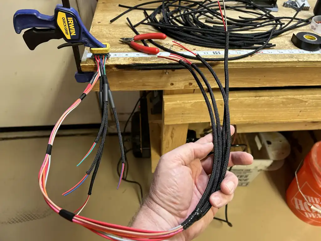

TPS (Throttle Position Sensor)
You only need one TPS, so I elected to use the front one. Try as I may, I couldn’t determine which TPS Accufab used on these throttle bodies so I had to get out my DMM to verify. A simple process illustrated here.
Before tying up all the harnesses permanently, I’d like to get the car running first to verify that all is good. So, I left it all loose for now.


Startup and Tuning
I went into the tune to change all of the engine parameters for the new setup – of which there are many. Injector type, fuel pressure, firing strategy, and prime and cranking percentages . . . which was a scientific wild ass guess. [That would need some love later . . . ]
My buddy Seth was on the way to help with startup as it’s always a good idea to have a 2nd set of eyes to look for fuel leaks, unplugged vacuum ports, etc at this point. You can never been too safe with fuel systems and fuel injectors**.
**Don’t assume that the compressed air you blew through those newly made fuel lines is all you need to flush them of debris. NEVER make that mistake – even tiny bits of debris can clog up a brand new $150 injector! Take a minute, and run some fuel through the fuel lines, fittings, fuel rails, etc. and empty that into a catch can. You’ll be surprised at what you find. We did that for the main feed to the distribution block as well as the return lines from the fuel rails to the regulator and yep, we got some rubber and metal bits in the catch can.
Afterwards, we reconnected all the lines, and checked for leaks (at the old pressure, 23psi). None to be found.


Challenge #5 – While we were raising the fuel pressure to 43psi, we had fuel spraying out of the fuel pressure sending unit in the regulator (this allows the HP ECU to datalog fuel pressure). Were we done for the evening? Nope! My buddy Brian Manske had several on hand. An hour later, we had this swapped out and were ready!
After diagnosing the rear IAC was defective (an hour of head scratching), plugging the idle passage in the rear throttle body, and modifying the tune accordingly, I was rewarded with a nice, smooth idle.
All in all, I think the project went quite smoothly. You’re just going to run into challenges along the way. If you try to tackle all aspects of a job like this one at the same time, these challenges can turn into obstacles that conspire to leave you frustrated and keep your vehicle on the sidelines. A systematic approach is always best.
So, how does it run? The biggest difference that I can tell is that the throttle response is just instantaneous. Crisp and clean. It also runs down the road just as smooth as can be.
If I had to guess why that was, I’d guess:
- Better atomization of the fuel due to the higher fuel pressure
- A more finely atomized mixture due to how the injectors work in this setup – four bank to bank – as compared to the TBI setup
- A more even fuel distribution above the rotors, translating to a more even distribution in the intake manifold – blowers with three lobe rotors (as mine is) tend to push the mixture forward in the manifold as a function of the design of the rotor
As of this writing, I’ve put several hundred miles on it. The idle definitely hunts a lot after startup – at least until the system gets into closed loop. So, I’ve got a bit of work to do there if i want to smooth that out . . . but for blower engines, folks do love that sound. I’ve still not been able to make a wide open throttle hit with the new 509. Hopefully that comes this fall! Stay tuned for that.


Parts Used from our Selection
Admittedly, it’s nice to be able to have access to all of these cool components when tackling a job as this one. I used the following:
- 20 AWG GXL Primary Wire – we offer this by the foot in 14 colors in 16 AWG, 18 AWG, and 20 AWG
- Semi-Rigid Wrappable Split Braided Tubing – we offer this in 10 foot or 25 foot lengths or EZ-Feed boxes, from 1/8″ to 1″ in diameter
- Metri-Pack Connectors – we offer the 150 Series, 150.2 Series, 280 Series, 480 Series, and 630 Series in all kinds of configurations
- Adhesive Lined Heat Shrink – we offer this in red and black from 1/8″ to 1 1/2″ ID in two different wall thicknesses
Of course my Books on Wiring & EFI can be hugely beneficial to inspire you, give you insight on how to tackle projects as this one, and walk you through the methodology I’ve used for decades.
So that’s it for Part 4. Man, the Olds’ has come a long way . . . what’s next? Stay tuned to find out!


